Loading...
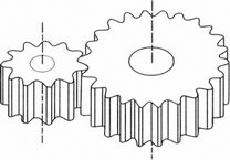 SPUR GEAR |
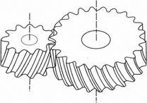 HELICAL GEAR |
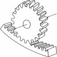 INTERNAL GEAR |
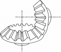 STRAIGHT BEVEL GEAR |
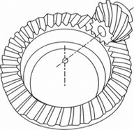 SPIRAL BEVELGEAR |
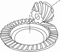 ZEROL BEVELGEAR |
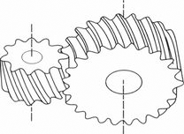 CROSSED HELICAL GEAR |
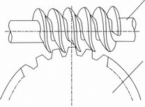 WORM GEAR |
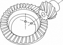 HYPOID GEAR |
GENERAL TYPE OF GEARHEAD

① means that the flange size is ㅁ80mm.
② is the shape of cutting.
③ is a ratio. There are 24 ratios from 1/3 to 1/200.
④ means a bearing type.
B : ALL BEARING TYPE
C : BALL BEARING + METAL BEARING,
M : ALL METAL BEARING TYPE
* If you need a ratio greater than 1/200, you can use an inter-decimal gearhead K8G10BX(1/10).
* K8G is adapted to 25W motor.
STRONG & SUPER-STRONG TYPES OF GEARHEAD

① means that the flange size is ㅁ90mm.
② is the shape of cutting.
③ is a ratio. There are 20 ratios from 1/3 to 1/180.
④ means a bearing type.
Strong types and super-strong types of gearheads are only in ball bearing types.
⑤ is a sign of strong type and super-strong type
No-Sign : Strong rectangle box type
F : Strong flange type
U : Super-strong type
UF : Super-strong flange type
* If you need a ratio greater than 1/180, you can use a decimal gearhead K9P10BX.
* K9P is adapted to 60W or 90W motor.
FOR EXAMPLE, REFER TO (BELOW FIG.)

* Care should be taken when doing assembly because only if the size of combing side and the shape of cutting are the same, they can be combined.
WHEN USING A DECIMAL GEARHEAD TOGETHER, REFER TO (BELOW FIG.)

If you need bigger gear ratio which can not be got by gearhead itself, you can use the decimal gearhead. The number of rotations are reduced by 1/10 but the ambient torque would not be increased because the ambient torque already fixed on gearhead.

NG : Revolutions of a gearhead (rpm)
NM : Revolutions of a motor (rpm)
i : gear ratio of a gearhead

(TABLE 1) THE ROTATING DIRECTION OF THE OUTPUT SHAFT IN THE GEARHEAD

The output torque when the gearhead is combined is calculated as follows. Refer to (Table 2) Transfer efficiency of gearhead

TG : Torque of a gearhead's output shaft
TM : Torque of a motor
i : Reduction ratio of a gearhead
η : Delivery efficiency of a gearhead.
(TABLE 2) DELIVERY EFFICIENCY OF GEARHEAD


The lifetime of the gearhead is usually determined by how the shaft is supported. However, since the load varies in general, the lifetime of the gearhead is determined by the service factor based on the load. Refer to (Table 3).
If the gearhead is used within the permissible torque, the rated lifetime of the gearhead is 5,000Hr for the ball bearing type and 2,000Hr for the metal type.
In case the gearhead operates as following conditions, the rated lifetime of the gearhead is the hours that it is impossible for the motor torque from the output shaft of the gearhead to convey and the gearhead has to stopped.
1. Torque : within the permissible torque
2. Load : Operating load in a constant direction without any load change
3. Operating hours: 8 hours a day
4. Temperature of the bearing : Metal type - 50℃ / Ball bearing type - 80℃
Temperature of the bearing : Metal type - 50℃ / Ball bearing type - 80℃
If a ball bearing type of gearhead is operating for 24 hours a day, the service factor should be taken into account. Therefore, a motor and a gearhead which have biggest permissible torque should be selected.
(TABLE 3) EXAMPLE OF LOAD AND SERVICE FACTOR
| Type of Load | Example of Load | SERVICE FACTORY | ||
|---|---|---|---|---|
| 5 hours a day | 8 hours a day | 24 hours a day | ||
| General Load | Belt Conveyor, Continuous operation in one direction | 0.8 | 1.0 | 1.5 |
| Medium Load | Frequent starting/operating, Frequent CAM driving | 1.2 | 1.5 | 2.0 |
| Medium Load | Instantaneous reversal operation, Instantaneous stopping | 1.5 | 2.0 | 2.5 |
| Heavy Impact Load | Very frequent occurrence of medium impact load operation | 2.0 ~ 2.5 | 2.5 ~ 3.0 | 3.0 ~ 3.5 |
(TABLE 4) STANDARD LIFETIME
| BALL BEARING TYPE | 5,000 hour |
|---|---|
| METAL TYPE | 2,000 hour |
The overhung load is loaded where the places between more than two supporting mechanisms are not on the shaft.

(TABLE 5) LOAD COEFFICIENT BY DRIVING METHOD
| Driving Method | K |
|---|---|
| CHAIN,SPROCHET | 1 |
| Gear | 1.25 |
| V-BELT | 1.5 |
| PLATE-BELT | 2.5 |

(TABLE 6 ) PERMISSIBLE OVERHUNG LOAD AND PERMISSIBLE THRUST LOAD
| MODEL | GEAR RATIO | Maximum Ambient Torque (kgf,㎝) |
Permissible Overhung Load (kg) |
Permissible Thrust Load (kg) |
|---|---|---|---|---|
| K6G□B(C) | 3 ~ 18 | 30 | 5 | 3 |
| 20 ~ 250 | 12 | |||
| K7G□B(C) | 3 ~ 18 | 50 | 8 | 4 |
| 20 ~ 200 | 45 | |||
| K8G□B(C) | 3 ~ 18 | 80 | 10 | 5 |
| 20 ~ 250 | 20 | |||
| K9G□B(C) | 3 ~ 18 | 100 | 25 | 10 |
| 20 ~ 200 | 30 | |||
| K9P□B K9P□BF |
3 ~ 10 | 200 | 40 | 15 |
| 12.5 ~ 20 | 45 | |||
| 25 ~ 200 | 50 | |||
| K9P□BU K9P□BUF |
3 ~ 10 | 300 | 40 | 15 |
| 12.5 ~ 20 | ||||
| 25 ~ 200 | ||||
| K10H□B | 3 ~ 36 | 400 | 55 | 20 |
| 40 ~ 200 | 65 |
*Note

| GEAR HEAD SIZE | MOTOR | Heat Treatment (Yes/No) | BEARING TYPE | Remark | ||
|---|---|---|---|---|---|---|
| ALL BALL BEARING | BALL BEARING+ METAL BEARING |
METAL BEARING | ||||
| □60mm | 6W | No | K6G□B | K6G□C | K6G□M | |
| □70mm | 15W | No | K7G□B | K7G□C | K7G□M | |
| □80mm | 25W | No | K8G□B | K8G□C | K8G□M | |
| □90mm | 40W | Yes,No | K9G□B | K9G□C | K9G□M | |
| 60W~200W | Yes | K9P□B | BOX TYPE | |||
| K9P□BF | FLANGE TYPE | |||||
| 60W~200W | Yes | K9P□BU | BOX TYPE | |||
| K9P□BUF | FLANGE TYPE | |||||
| □104mm | 200W | Yes | K10H□B | |||
To facilitate fastening a load to the gearhead output shaft, there is a groove in the key and D-cut in the smaller gearhead. Refer to (Fig.6)


