Loading...

T : Torque
J : Inertia moment
ω : Angular velocity
t : Time
n : Rotational velocity
GD² : FLYHEEL 효과 [GD² =4J]
g : Gravitational acceleration (g = 9.8[m/sec2]
α : Angular acceleration

| Circulular Disk | Hollow | |
|---|---|---|
| Shape |
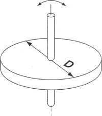
|
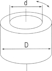
|
| GD² Equation |
 W : Mass(kgf) D : Outer Diameter(㎝) |
 W : Mass(kgf) D : Outer Diameter(㎝) |
| Sphere | Hexahedron | |
|---|---|---|
| Shape |
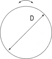
|
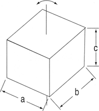
|
| GD² Equation |
 W : Mass(kgf) D : Outer Diameter(㎝) |
 W : Mass(kgf) a,b : Length of Side(㎝) |
| POLE | ||
|---|---|---|
| Shape |
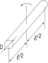
|
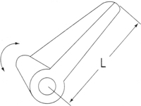
|
| GD² Equation |
 W: : Mass(kgf) D : Outer Diameter(㎝) ℓ : Length(㎝) |
 W : Mass(kgf) ℓ : Length(㎝) |
| Linear Motion (Horizontal) | Linear Motion (Vertical) | |
|---|---|---|
| Shape |
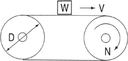
|
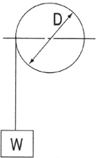
|
| GD² Equation |
 V : Conveyor Speed (cm/min) N : Drum Rotational Speed (rpm) W : Weight Over Conveyor(kgf) D : Drum Outside Diameter (㎝) (Not included GD² for belt and drum) |
GD² : WD² [kgf·㎠] W : Mass(kgf) D : Diameter(㎝) |
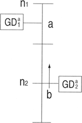
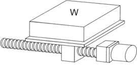
| Gearhead | Operation of Ball Screw | |
|---|---|---|
| Shape |
|
|
| GD² Equation | a-axis component of tatal GD² n₁ : Rotational speed of a-axis n₂ : Rotational speed pf b-axis Reduction ratio is n₁/n₂(i >1) |
 GD²1 : Ball Screw GD² P : Pitch of Ball Screw(㎝) W : Total weight of table and work |
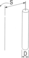
| GD² of Arbitrary shaft | ||
|---|---|---|
| Shape |
|
|
| GD² Equation |
 D : Diameter (㎝), W : Mass (kgf), S : Radius of Rotation (㎝) |
|

Flywheel Effect
J : Inertia Moment

GDM : Motor Axis Component of GD²
GDL² : Assembled Load of GD² on Gearhead
i : Reduction Ratio of a Gearhead


g : Gravitational Acceleration 9.80665 [m/sec²]
EXPLICIT CALCULATION METHOD OF MOTOR CAPACITY
| SIZE | Output | Allowable inertia load in the motor shaft |
|---|---|---|
| GD²[kg.fcm] | ||
| □ 60 | 6W | 0.25 |
| □ 70 | 15W | 0.57 |
| □ 80 | 15W,25W | 1.20 |
| □ 90 | 40W | 3.00 |
| □ 90 | 60W | 3.00 |
| □ 90 | 90W,120W,150W | 4.60 |
| □ 90 | 80W,200W | 6.00 |
Gear ratio 1/3~1/5

Gear ratio 1/60우

GD²G : Allowable inertia in gearhead shaft
GD²M : Allowable inertia in motor shaft
i : Gear ratio of Gear Head