Loading...
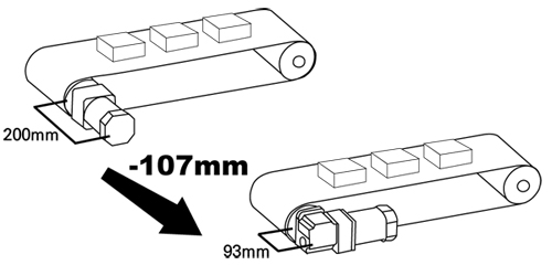
Offering a wide range
20 kinds of wide range from 3 up to 180 gear ratio is supplied. You can choose optimum gear ratio like parallel gearhead.Max allowable torque is same as parallel gearhead.
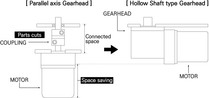
Costs Saving
BRH gearhead contributes components cost saving, assembly process number saving by removing connected components.

| ① + ② | GEARHEAD Installation size + PINION TYPE | |
| 8G : 80mm (G)GENERAL 9P : 90mm (P)POWERFUL | ||
| ③ | Ratio | 180(180:1) |
| ④ | BRH : Right Angle Gearhead·Hollow Shaft type BRS : Right Angle Gearhead·Solid Shaft type | |
| Hollow Shaft type(BRH) | Solid Shaft type(BRS) | ||
| GEARHEAD Model | Ratio | GEARHEAD Model | Ratio |
| K8G□BRH | 3~180 | K8G□BRS | 3~180 |
| K9P□BRH | 3~180 | K9P□BRS | 3~180 |
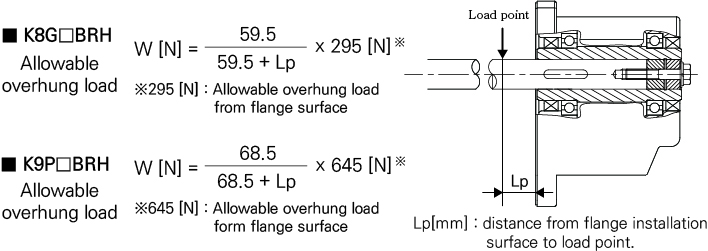
| Model | Ratio | Maximum permissible Torque | Permissible overhung load (N) | Permissible Thrust load | |
| N.m | 10mm from shaft end | 20mm from shaft end | N | ||
| K8G□BRH | 3~180 | 8 | 250 | 220 | 100 |
| K9P□BRH | 3~180 | 20 | 560 | 500 | 250 |
| K8G□BRS | 3~18 | 8 | 100 | 150 | 100 |
| 25~180 | 200 | 300 | |||
| K9P□BRS | 3~9 | 20 | 400 | 500 | 250 |
| 12.5~25 | 450 | 600 | |||
| 30~108 | 500 | 700 | |||
| Ratio | 3 | 3.6 | 5 | 6 | 7.5 | 9 | 12.5 | 15 | 18 | 25 | 30 | 36 | 50 | 60 | 75 | 90 | 100 | 120 | 150 | 180 | |
| K8G□BRH | Rated | 40% | 50% | 60% | |||||||||||||||||
| K9P□BRH | Rated | 50% | 68% | 60% | 50% | ||||||||||||||||
| K8G□BRS | Rated | 40% | 50% | 60% | |||||||||||||||||
| K9P□BRS | Rated | 68% | 60% | 50% | |||||||||||||||||
Unit : mm
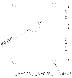
| Model | Bolt size | Installation holes dimensions | |||||
| Thickness of Flange | A | B | C | ØD | ØE | ||
| K8G□BRH | M5 | 9 | 28 | 55 | 25 | Ø16 | Ø5.5 |
| K8G□BRS | Ø35 | ||||||
| K9P□BRH | M8 | 12 | 30 | 67 | 33 | Ø18 | Ø8.5 |
| K9P□BRS | Ø35 | ||||||
| ※The code in □ of gearhead name is for gear ratio. | |||||||
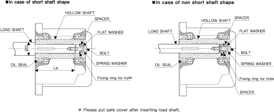
Unit : mm
| ITEM | K8G□BRH | K9P□BRH |
| Inner diameter of hollow shaft (H8) |  |  |
| Diameter of load shaft (h7) |  |  |
| Diameter for hole fixing ring | Ø15 C Type fixing ring | Ø17 C Type fixing ring |
| applicable bolt | M5 | M5 |
| Thickness of spacer | 4 | 4 |
| Outdiameter D of short load shaft | 25 | 30 |
| La dimension of short load shaft | 58~60 | 68~70 |
| ※Do spacer thickness as dimension of table. Exceeded dimension can`t put safe cover by bolt coming out ※ Fixing Ring, Spacer, Bolt to install load shaft are not attached. Please arrange them by yourself. | ||