Loading...
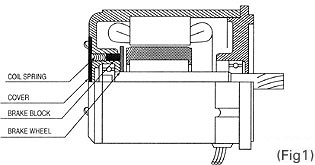
- It is possible for the motor to operate in rotational direction from normal - stop - to reverse.
- The reversible motor has a temporary brake device built inside the motor to facilitate the operation in normal as well as reverse direction. Also, the mail and sub windings of the stator have their windings manufactured with the same method to guarantee the identical characteristics between them. Refer to (Fig. 2).
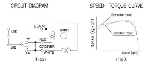
- Also, it has a higher starting torque to facilitate the frequent changes in rotational direction from normal direction to reverse direction, and vice versa, within a short time. Refer to (Fig. 3).
- The temporary brake is employed to prevent overrun. The temporary brake has a little retaining force to provide excellent instantaneous stop by preventing overrun when stopping. Refer to (Fig. 1).
- The changeover switch can help the motor reverse its rotational direction easily within a short time so that it is suitable for such operation that changes the rotational direction frequently from normal toreverse, and vice versa. Therefore, this motor is called a reversible motor.
- Since the design characteristic of the reversible motor is a capability to control the directional changes in rotation, the loss input is larger and the temperature can rise higher compared with the induction motor. Hence, the rated operating time is limited to 30 minutes.
- Thus, 30 minutes of rated operating time means that the motor at the rated load can have at least 30 minutes of non-stop operation within the safe upper limit of the temperature rise. It is possible for the motor at the intermittent load or at the light load to have non-stop operation, if only the outer cover temperature is not over 90℃.
- In general, the reversible motor is as same as the induction motor in terms of the number of rotation, and the characteristics of torque, voltage, and condenser.
- The temporary brake of the reversible motor has characteristics as follows.
① Apply a frictional load to improve the frequent reversal operation.
② Reduce overrun.
③ Provide a little holding torque.
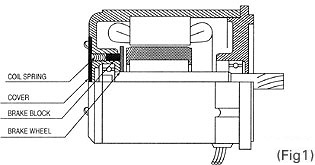
- Structurally, as shown in (Fig. 1), the brake block is forced toward the brake wheel by a spring to make retention force.
- Since at the aspect of the structure of the brake as shown the above it has a limitation to strengthen retention force, we adjusted the brake power to be about 10% of the motor output torque.
- The figures representing the holding torque and the overrun under no-load in (Table 1) may have more or less deviations for each motor. They may also have some discrepancies depending on the operating duration and the ambient temperature.
- The rated torque and electric current of the reversible motor were measured in the circumstance where the temporary brake block is installed in the motor. Therefore, there will be no problem even if the corresponding table figures are used when selecting a motor. The conservative selection of a motor is recommended, however, because the figures may have some deviation depending on the brake block employed for the motor.
- Care should be given, because there is a case that the holding toque may fall below the figures of (Table 1) in the initial phase of operation.
| PHASE | SIZE | OUT PUT(W) | MOTOR MODEL | HOLDING TORQUE | OVER RUN | |
|---|---|---|---|---|---|---|
| (g · cm) | (N· cm) | |||||
| SINGLE PHASE | 60mm | 6 | K6RG6N□ | 50 | 0.5 | 4 |
| 70mm | 15 | K7RG15N□ | 130 | 1.3 | 5 | |
| 80mm | 25 | K8RGP25N□ | 150 | 1.5 | 5 | |
| 90mm | 40 | K9RG40N□ | 400 | 4.0 | 6 | |
| 60 | K9RP60F□ | |||||
| 90 | K9RP90F□ | |||||
- Although 30 minutes of rated operating time is specified for the reversible motor, the rated operating time may change depending on the operation conditions if the operation frequently repeats stop and run (On-Off)within a short period of time.
- If the reversible motor frequently repeats stop and run (On-Off) within a short time, the starting current gets increased to cause the motor temperature to rise. However, the longer rated operating time may be obtained by allowing the motor to remain stop longer, because the stoppage can provide a chance of natural cooling for the motor to decrease its temperature.
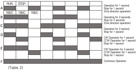
- The conditions of the intermittent (On-Off) operation are determined as shown in A ~ F of (Fig. 4). F stands for continuous operation.
- The characteristic values from (Fig. 4) to (Fig. 7) are the result of the characteristic value when measured with a 220V 60㎐ motor according to A ~ F of the operating conditions (Table 2). Therefore, since the characteristic voltage of 220V 60㎐ is about 10% higher, the characteristic value is also slightly higher, so be careful to use it under the allowable temperature.
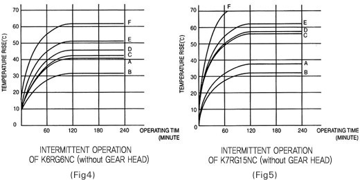
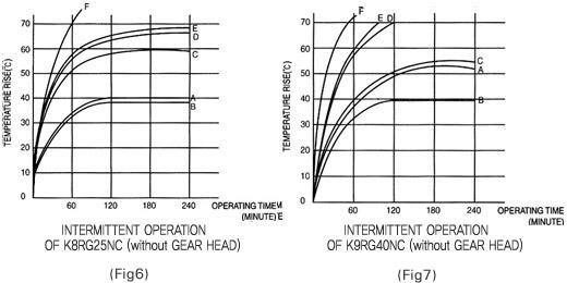
- The temperature rise measurement is performed when the motor, under no-load, is prevented rom transferring its internal heat to the outside through the motor's external contact points using thermograph. This method of measurement can provide the highest possible temperature rise.
- Especially, if either a load or an inertia load is greater than the motor's rated torque, the longer time is required for start or directional reversal, resulting in a greater temperature rise, which requires a user's attention.
- The specified temperature rise of the reversible motor is 75℃ (△T value) in general, and be careful not to exceed the temperature.
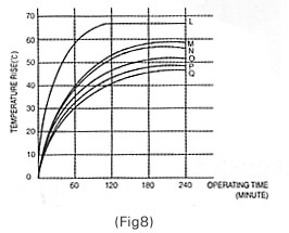
- In reality, there is a case that the motor alone is used, but mostly the motor is used in combination with the gearhead. Hence, when the motor of K8R25N is used with no-load in combination with the gearhead of K8G50B, the temperature rise is like a L curve shown in (Fig. 8) and also the temperature rise becomes lower and the operating time becomes longer by about 30 minutes as compared with the motor shown in (Fig. 7). (Table 2) shows various heat radiation plates for mounting surface. The table indicates that the temperature decreases by about 6℃ when the diameter of the heat radiation plate is doubled, and the greater heat conductivity of aluminum makes the aluminum temperature rise smaller than that of the steel. Also, the temperature can be lowered by about 3℃ if the aluminum is painted.
- Although the principle is to keep the coil temperature below the specified temperature for the insulation class. It is possible to continue the operation if the motor housing surface temperature remains less than 90℃. The temperature of the motor varies depending on the load, operating cycle, motor's mounting method, and ambient temperature.
GENERAL SPECIFICATION OF REVERSIBLE MOTORS
| ITEM | SPECIFICATION |
|---|---|
| Insulation Resistance | 100MΩ or more when 500V megger is applied between the windings and the housing after rated motor operation under normal ambient temperature and humidity |
| Dielectric Strength | Sufficient to withstand 1500V at 50/60Hz applied between the windings and the case after rated motor operation under normal ambient temperature and humidity for 1 min. |
| Temperature Rise | Class A (below 65deg), class E (below 75deg), class B (below 85deg) (measured by thermometer after rated operation) |
| Insulation Class | Class E(120℃), Class B(130℃), UL approval motor class A (105℃) |
| Overheat Protection Device | Built-in thermal protector (automatic return type):Open 130℃±5℃ Close 82℃±15℃ |
| Ambient Temperature | -10℃~50℃ (with UL, CE marked motors: -10℃~40℃) |
| Ambient Humidity | 85% maximum (non condensing) |